Software simulation in ROS can help you learn about how to make robots “think.” It is a long way to go from a line following bot to a self-driving car! This makes software development one of the hardest fields to explore for enthusiasts. This is where the Robot Operating System (ROS) comes in. The highly modular nature of ROS facilitates a developer to focus on their domain and use one of the many open-source ROS packages to fill in the gaps.
In this project, I developed a ROS package that implements SLAM and Autonomous Navigation on a custom 2 wheeled Differential Drive robot in Gazebo. Throughout the development of this project, I learnt several new ROS concepts which are essential to understand for any beginner. In these posts, I will summarise the steps that I followed (along with relevant links) and hopefully, by the end, you would have learnt something new.
Bur first, let’s watch the final result:
To follow along, I would suggest that you install the ROS package using the instructions in the GitHub Repository1. You can find the same here.
URDF and Sensors
We will be using Gazebo as a simulation environment for our purposes, so, we need to describe the robot model in a way that Gazebo can understand it. The Unified Robotic Description Format (URDF) comes to our aid here. URDF describes all the physical properties of a robot, like its basic blocks (links), how links move relative to one another (joints), inertial properties of the links, visual appearance in Gazebo, collision properties, etc.
Apart from that, as we are working in a simulation environment, we will need the robot to get sensor data like LIDAR point clouds, camera feed, etc. We also need a way to move the robot in Gazebo. All these are done using Gazebo plugins.2
So now, let’s look at the URDF for our robot. There are 4 files located in the ~/urdf/ folder:
- mybot.xacro
- materials.xacro
- mybot.gazebo
- macros.xacro
URDF is written in XML. And as you can see, it gets a bit complicated when dealing with many links and joints. To avoid rewriting certain blocks of code, we can use Xacro. Xacro effectively gives us shortcuts to help reduce the overall size of the URDF file which makes it easier to read and maintain. I followed the ROS Wiki URDF Tutorials3 to learn about URDF and Xacros.
The mybot.xacro file is our main URDF. It specifies all the joints, links, sensors. You can see that we are importing the other files using:
<xacro:include filename="$(find diff_drive_bot)/urdf/mybot.gazebo" />
<xacro:include filename="$(find diff_drive_bot)/urdf/materials.xacro" />
<xacro:include filename="$(find diff_drive_bot)/urdf/macros.xacro" />
Let’s look at a code snippet from mybot.xacro:
<link name='chassis'>
    <pose>0 0 0.1 0 0 0</pose>

    <inertial>
      <mass value="15.0"/>
      <origin xyz="0.0 0 0.1" rpy=" 0 0 0"/>
      <inertia
          ixx="0.1" ixy="0" ixz="0"
          iyy="0.1" iyz="0"
          izz="0.1"/>
    </inertial>

    <collision name='collision'>
      <geometry>
        <box size=".4 .2 .1"/>
      </geometry>
    </collision>

    <visual name='chassis_visual'>
      <origin xyz="0 0 0" rpy=" 0 0 0"/>
      <geometry>
        <box size=".4 .2 .1"/>
      </geometry>
    </visual>
</link>
Here, we are defining a link chassis and specifying its visual, inertial and collision properties. To describe the joints between 2 links, we use:
<joint type="continuous" name="left_wheel_hinge">
    <origin xyz="0 0.15 0" rpy="0 0 0"/>
    <child link="left_wheel"/>
    <parent link="chassis"/>
    <axis xyz="0 1 0" rpy="0 0 0"/>
    <limit effort="10000" velocity="1000"/>
    <joint_properties damping="1.0" friction="1.0"/>
</joint>
Here, the joint between left_wheel and chassis is called left_wheel_hinge and is a continuous type hinge. Meaning it rotates about its axis with no limits. Learn more about all 6 types of URDF joints here.4
The mybot.gazebo file contains the gazebo plugins for the differential drive motion and sensors. The materials.xacro contains all the colour RGB values that we use in mybot.xacro and mybot.gazebo. Finally, macros.xacro contains all the macros for mathematical equations used to define the robot. It’s not being used in this case because we have fixed all the values. But if you were to change the dimensions of your robot, you can use the macros.xacro file to avoid calculating the other related dimensions.
Again, to learn how to write URDF and use Xacro, the ROS Wiki tutorial3 series is a good place to start.
Gazebo and Rviz
Gazebo is an open-source 3D robotics simulator. This means that it is essentially a replacement for the “Real World”. Developers can test their algorithms on Gazebo first, iron out the bugs and then finally build and implement on a real robot. Rviz stands for ROS visualization. At any instant, several ROS nodes are publishing and subscribing messages on various topics. Some of these messages are difficult to understand by just reading the values. Rviz helps us visualize the message data. E.g., LIDAR point clouds are displayed as dots in Rviz, making it much more intuitive than seeing thousands of numbers in an array.
Let’s spawn our robot in Gazebo:
$ roslaunch diff_drive_bot gazebo.launch
The ROS launch5 file gazebo.launch starts up the ROS core, Gazebo, and spawns our robot in an empty world with the House model as the robot’s environment.
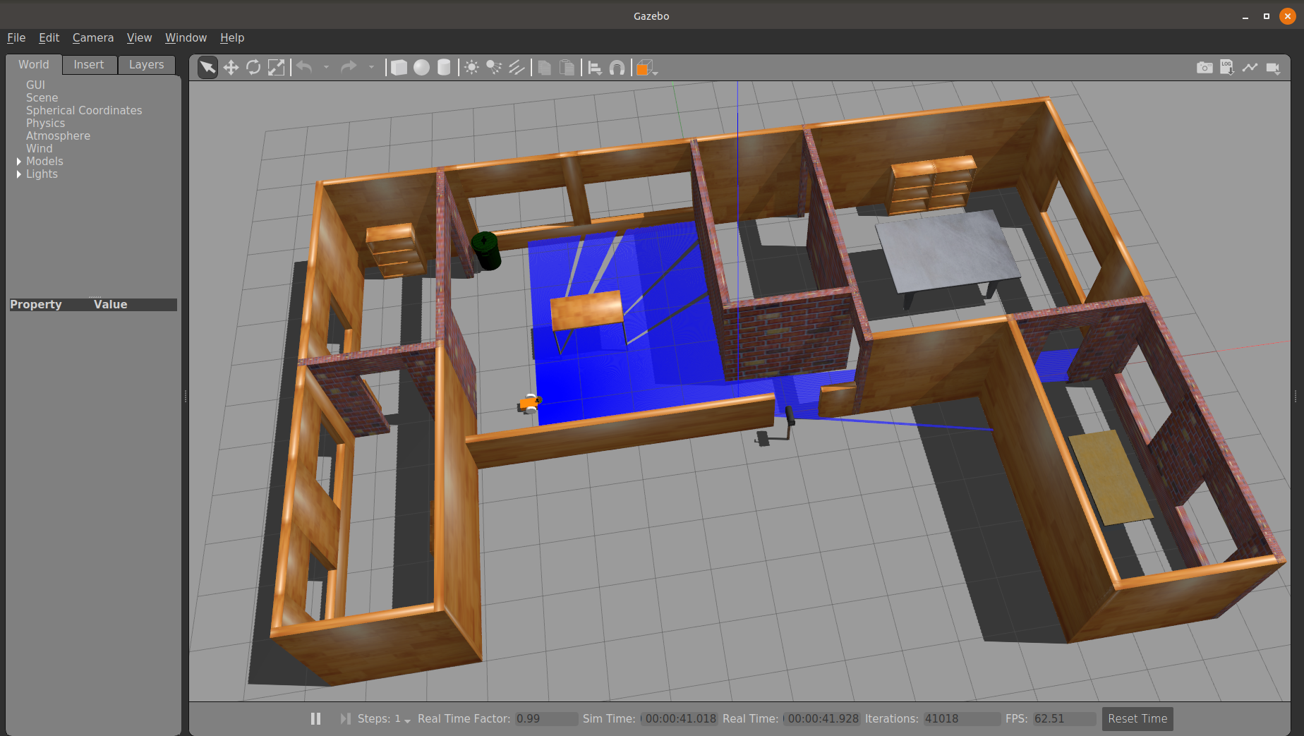
You can see that LIDAR’s laser bouncing off on the walls and objects of the environment. Now let’s start Rviz:
$ roslaunch diff_drive_bot rviz.launch
This launch file sets the robot_description parameter to our robot URDF and publishes the joint and robot states. These are essential to publish because otherwise, Rviz won’t know how the robot links transform.
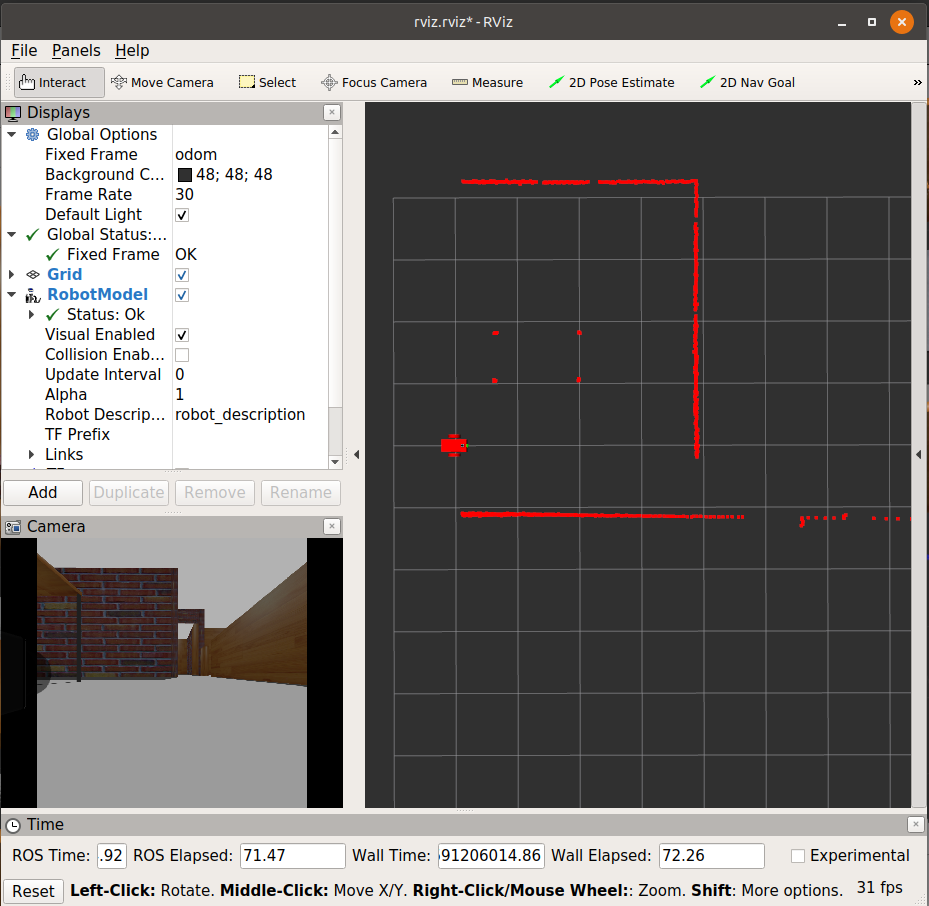
You can see in Rviz that the LIDAR data published on the scan topic is visualised as red dots, showing the obstacles and walls in the robot’s path.
Teleoperation
Now that we setup the URDF, Sensors and watched the robot in Gazebo and the sensor data in Rviz, its time to move the robot! For the purpose of this demonstration, I modified the turtlebot3 keyboard teleoperation node to suit our needs. To use that, execute:
$ rosrun diff_drive_bot keyboard_teleop.py
You would now be able to move the robot around in Gazebo. Observe how the Rviz laser scan point cloud also changes as the robot moves around in the environment.
With that, this little tutorial/guide is over. I hope that you learnt something new about URDF, Sensors and how to visualise them in Gazebo and Rviz. If you have any questions/suggestions, feel free to drop them below. In the next post, I will share how I implemented SLAM and the ROS Navigation stack on the above robot.